
In the Steel Design add-on, you can apply a value for cold-formed sections according to EN 1993‑1‑3, which performs the stability analysis and cross-section design according to Sections 6.1.2 - 6.1.5 and 6.1.8 - 6.1.10.
Go to Explanatory Video
In the "Steel Joints" add-on, you can consider preloaded bolts in all components during the calculation. You can easily activate the preloading using the check box in the bolt parameters, and it has an impact on the stress-strain analysis as well as the stiffness analysis.
Preloaded bolts are special bolts used in steel structures to generate a high clamping force between the connected structural components. This clamping force causes friction between the structural components, which allows for the transfer of forces.
Functionality
Preloaded bolts are tightened with a certain torque, causing them to stretch and generate a tensile force. This tensile force is transferred to the connected components and leads to a high clamping force. The clamping force prevents the connection from loosening and ensures safe force transmission.
Advantages
- High load-bearing capacity: Preloaded bolts can transfer large forces.
- Low deformation: They minimize the deformation of the connection.
- Fatigue strength: They are resistant to fatigue.
- Easy assembly: They are relatively easy to assemble and disassemble.
Analysis and Design
The calculation of preloaded bolts is performed in RFEM using the FE analysis model generated by the "Steel Joints" add-on. It takes into account the clamping force, friction between structural components, shear strength of bolts, and load-bearing capacity of the structural components. The design is carried out according to DIN EN 1993‑1‑8 (Eurocode 3) or the US standard ANSI/AISC 360‑16. You can save the created analysis model, including the results, and use it as an independent RFEM model.

The initial stiffness Sj,ini is a decisive parameter for evaluating whether a connection can be characterized as rigid, non-rigid, or hinged.
In the “Steel Joints” add-on, you can calculate the initial stiffnesses Sj,ini according to Eurocode (EN 1993-1-8 Section 5.2.2) and AISC (AISC 360-16 Cl. E3.4) in relation to the internal forces N, My, and/or Mz.
The optional automatic transfer of initial stiffnesses allows for a direct transfer as member end hinge stiffnesses in RFEM. Then, the entire structure is recalculated and the resulting internal forces are automatically adopted as loads in the calculation and design of the connection models.
This automated iteration process eliminates the need for manual export and import of data, reducing the amount of work and minimizing potential sources of error.
Explanatory Video: Calculation of Initial Stiffness Sj,ini
Would you like to perform cross-section design checks for cold-formed steel members according to EN 1993‑1‑3? No matter if you design the cold-formed sections from the cross-section library or the general cold-formed (non-perforated) sections from RSECTION – your structural analysis program helps you to determine the effective cross-section, taking into account the local buckling and instability. You can also perform a cross-section check according to EN 1993‑1‑3, 6.1.6. In this case, the internal forces from the calculation using Torsional Warping (7 DOF) are taken into account by means of the equivalent stress check
Go to Explanatory Video
The Aluminum Design add-on provides you with further options. Here you can also design general cross-sections that are not predefined in the cross-section library. For example, create a cross-section in the RSECTION program and then import it into RFEM/RSTAB. Depending on the design standard used, you can select from various design formats. This includes, for example, the equivalent stress analysis.
With a license for RSECTION and Effective Sections, you can also perform the design checks while taking into account the effective cross-section properties according to EN 1993‑1‑5.

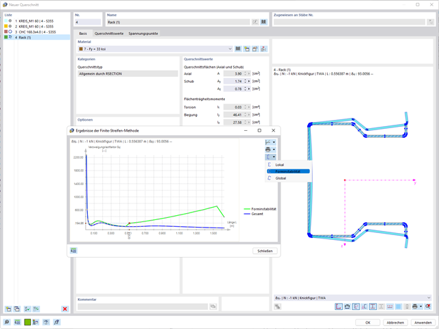
When performing a design according to EN 1993‑1‑3, it is possible to graphically display a mode shape for the distortional buckling of a cross-section, and for the RSECTION cross-sections.
The mode shape can also be output in RSECTION 1 for library cross-sections.

- The design of the connection components is carried out according to AISC 360-16 and Eurocode EN 1993-1-8.
- After activating the add-on, the design situations for steel joints must be activated in the "Load cases and Combinations" dialog box.
- The "Structure Stability" add-on is required for the connection stability design (buckling).
- The calculation can be started via the table or the icon in the top bar.

- Calculation of deflections and comparison with the normative or manually adjusted limit values
- Consideration of a precamber for the deflection analysis
- Different limit values are possible, depending on the design situation type
- Manual adjustment of reference lengths and segmentation by direction
- Calculation of deflections related to the initial structure or to the deformed structure
- Further detailed design checks depending on the selected design standard (for example, limitation of web breathing according to EN 1993‑2)
- Graphical result display integrated in RFEM/RSTAB; for example, the design ratio of a limit value, the deformation, or the sag
- Complete integration of the results into the RFEM/RSTAB printout report

- Manual specification of critical component temperature or automatic determination of component temperature for desired duration
- A wide range of fire curves: standard temperature-time curve, external fire curve, hydrocarbon curve
- Manual adjustment of the essential coefficients for the determination of the steel temperature
- Consideration of hot-dip galvanizing of structural components for the determination of the steel temperature
- Results of a temperature-time diagram for the gas and steel temperature
- Fire protection cladding as a contour or a box cladding with temperature-independent materials can be considered when determining the temperature
- Design of members made of carbon steel or stainless steel
- Cross-section design checks and stability analyses (equivalent member method) according to EN 1993‑1‑2, Clause 4.2.3
- Design checks of the cross-sections of Class 4 according to EN 1993‑1‑2, Annex E.

The design checks for the members you have selected are carried out taking into account the governing component temperature. You can perform the cross-section design checks and stability analyses according to EN 1993‑1‑2, Section 4.2.3, in the Steel Design add-on. All reduction factors and coefficients that are necessary are stored accordingly and are taken into account when determining the load-bearing capacity.
The effective lengths for the equivalent member design are taken directly from the strength entries. You don't need to enter them again.
In each design, perform the cross-section classification first. For the cross-sections of Class 4, the design is performed automatically according to EN 1993‑1‑2, Annex E.

For the design according to Eurocode 3, the parameters of the National Annexes (NA) are integrated for the following countries:
-
 DIN EN 1993-1-1/NA:2020-11 (Germany)
 -
 ÖNORM EN 1993-1-1/NA:2015-12 (Austria)
 -
 SN EN 1993-1-1/NA:2016-07 (Switzerland)
 -
 BDS EN 1993-1-1/NA:2015-10 (Bulgaria)
 -
 BS EN 1993-1-1/NA:2016-07 (United Kingdom)
 -
 CEN EN 1993-1-1/2015-06 (European Union)
 -
 CYS EN 1993-1-1/NA:2015-07 (Cyprus)
 -
 CZE EN 1993-1-1/NA:2016-06 (Czech Republic)
 -
 DS EN 1993-1-1/NA:2015-07 (Denmark)
 -
 ELOT EN 1993-1-1/NA:2017-01 (Greece)
 -
 EVS EN 1993-1-1/NA:2015-08 (Estonia)
 -
 HRN EN 1993-1-1/NA:2016-03 (Croatia)
 -
 I S. EN 1993-1-1/NA:2016-03 (Ireland)
 -
 ILNAS EN 1993-1-1/NA:2015-06 (Luxembourg)
 -
 IST EN 1993-1-1/NA:2015-11 (Iceland)
 -
 LST EN 1993-1-1/NA:2017-01 (Lithuania)
 -
 LVS EN 1993-1-1/NA:2015-10 (Latvia)
 -
 MS EN 1993-1-1/NA:2010-01 (Malaysia)
 -
 MSZ EN 1993-1-1/NA:2015-11 (Hungary)
 -
 NBN EN 1993-1-1/NA:2015-07 (Belgium)
 -
 NEN EN 1993-1-1/NA:2016-12 (Netherlands)
 -
 NF EN 1993-1-1/NA:2016-02 (France)
 -
 NP EN 1993-1-1/NA:2009-03 (Portugal)
 -
 NS EN 1993-1-1/NA:2015-09 (Norway)
 -
 PN EN 1993-1-1/NA:2015-08 (Poland)
 -
 SFS EN 1993-1-1/NA:2015-08 (Finland)
 -
 SIST EN 1993-1-1/NA:2016-09 (Slovenia)
 -
 SR EN 1993-1-1/NA:2016-04 (Romania)
 -
 SS EN 1993-1-1/NA:2019-05 (Singapore)
 -
 SS EN 1993-1-1/NA:2015-06 (Sweden)
 -
 STN EN 1993-1-1/NA:2015-10 (Slovakia)
 -
 TKP EN 1993-1-1/NA:2015-04 (Belarus)
 -
 UNE EN 1993-1-1/NA:2016-02 (Spain)
 -
 UNI EN 1993-1-1/NA:2015-08 (Italy)

The Steel Design add-on helps you, among other things, to design general cross-sections that are not predefined in the cross-section library. To do this, create a cross-section in the RSECTION program and then import it into RFEM/RSTAB. Depending on the design standard that you have used, you can select from various design formats. One of them is, for example, the equivalent stress analysis. Do you have a license for RSECTION and Effective Cross-Sections? Then you can also perform the design checks that take into account the effective cross-section properties according to EN 1993‑1‑5.

Did you use the eigenvalue solver of the add-on to determine the critical load factor for the stability analysis? Verz well, you can then display the governing mode shape of the object to be designed as a result. The eigenvalue solver is available for the lateral-torsional buckling analysis, depending on the design standard used. You can also use the internal eigenvalue solver for the general method according to EN 1993‑1‑1, 6.3.4.

For joint components, you can check whether the stability failure is relevant. This requires the Structure Stability add-on for RFEM 6.
In this case, you calculate the critical load factor for all analyzed load combinations and the selected number of mode shapes for the connection model. Compare the smallest critical load factor with the limit value 15 from the standard EN 1993‑1‑1, Clause 5. Furthermore, you can make user-defined adjustment of the limit value. As a result of the stability analysis, the program displays the corresponding mode shapes graphically.
For the stability analysis, RFEM uses the adapted surface model to specifically recognize the local buckling shapes. You can also save and use the model of the stability analysis, including the results, as a separate model file.

Do you work with steel connections? The Steel Joints add-on for RFEM supports you when analyzing steel connections by using an FE model. In this case, the modeling runs fully automatically in the background. Nevertheless, you can control this process via the simple and familiar input of components. You can then use the loads determined on the FE model for your design of the components according to EN 1993‑1‑8 (including National Annexes).
More About Steel Joints
Compared to the RF‑/STEEL EC3 add-on module (RFEM 5 / RSTAB 8), the following new features have been added to the Steel Design add-on for RFEM 6 / RSTAB 9:
- In addition to Eurocode 3, other international standards are integrated (such as AISC 360, CSA S16, GB 50017, SP 16.13330)
- Consideration of hot-dip galvanizing (DASt guideline 027) in the fire protection design according to EN 1993‑1‑2
- Input option for transverse stiffeners that can be taken into account in the shear buckling analysis
- Lateral-torsional buckling can also be checked for hollow sections (for example, relevant for slender, high rectangular hollow sections)
- Automatic detection of members or member sets valid for the design (for example, automatic deactivation of members with invalid material or members already contained in a member set)
- Design settings can be adjusted individually for each member
- Graphical display of the results in the gross section or the effective section
- Output of the used design check formulas (including a reference to the used equation from the standard)
- Available for general thin-walled RSECTION cross-sections
- Classification according to
- EN 1993-1-1
- EN 1993-1-4
- EN 1999-1-1
- Determination of the effective section according to
- EN 1993-1-5
- EN 1993-1-3
- EN 1999-1-1
- Consideration of the effects of distortional buckling of cold-formed sections via eigenvalue method
- Determination of the stresses on the effective section and gross section
- Cross-section, stability, and serviceability limit state design checks of RSECTION cross-sections of Class 4 according to EN 1993‑1‑1 or EN 1999‑1‑1 in the Steel Design or Aluminum Design add-ons
- Cross-section checks for cold-formed RSECTION cross-sections according to EN 1993‑1‑3 in the Steel Design add-on
- Available for all National Annexes integrated in the Steel Design add-on
The program supports you: It determines the bolt forces on the basis of the FE analysis model and evaluates them automatically. The add-on performs the standard-compliant design of bolt resistance for failure cases, such as tension, shear, hole bearing, and punching, and clearly displays all required coefficients.
Do you want to perform weld design? The welds are modeled as elastic-plastic surface elements, and their stresses are read out from the FE analysis model. The plasticity criteria is set in the way that they represent failure according to AISC J2-4, J2-5 (strength of welds), and J2-2 (strength of base metal). The design can be performed with the partial safety factors of the selected National Annex of EN 1993‑1‑8.
The plates in the connection are designed plastically by comparing the existing plastic strain to the allowable plastic strain. The default setting is 5% according to EN 1993‑1‑5, Annex C, but can be adjusted by user-defined specifications, as well as 5% for AISC 360.

- Design of tension, compression, bending, shear, torsion, and combined internal forces
- Tension design with consideration of a reduced section area (for example, hole weakening)
- Automatic classification of cross-sections to check local buckling
- Internal forces from the calculation with Torsional Warping (7 DOF) are taken into account by means of the equivalent stress check (currently not for the design standards AISC 360‑16 and GB 50017).
- Design of cross-sections of Class 4 with effective cross-section properties according to EN 1993‑1‑3 (licenses for RSECTION and Effective Sections are required for the RSECTION cross-sections)
- Shear buckling check according to EN 1993‑1‑5 with consideration of transverse stiffeners
- Design of stainless steel components according to EN 1993‑1‑4

- Design of tension, compression, bending, shear, torsion, and combined internal forces
- Tension design with consideration of a reduced section area (for example, hole weakening)
- Automatic classification of cross-sections to check local buckling
- Internal forces from the calculation with Torsional Warping (7 DOF) are taken into account by means of the equivalent stress check (currently not yet for the design standard ADM 2020).
- Design of cross-sections of Class 4 with effective cross-section properties according to EN 1993‑1‑5 (licenses for RSECTION and Effective Sections are required for the RSECTION cross-sections)
- Shear buckling check with consideration of transverse stiffeners

- For the design according to Eurocode 3, the parameters of the National Annexes (NA) are integrated for the following countries:
-
DIN EN 1993-1-1/NA:2016-04 (Germany)
-
ÖNORM EN 1993-1-1/NA:2015-12 (Austria)
-
SN EN 1993-1-1/NA:2016-07 (Switzerland)
-
BDS EN 1993-1-1/NA:2015-10 (Bulgaria)
-
BS EN 1993-1-1/NA:2016-07 (United Kingdom)
-
CEN EN 1993-1-1/2015-06 (European Union)
-
CYS EN 1993-1-1/NA:2015-07 (Cyprus)
-
CZE EN 1993-1-1/NA:2016-06 (Czech Republic)
-
DS EN 1993-1-1/NA:2015-07 (Denmark)
-
ELOT EN 1993-1-1/NA:2017-01 (Greece)
-
EVS EN 1993-1-1/NA:2015-08 (Estonia)
-
HRN EN 1993-1-1/NA:2016-03 (Croatia)
-
I S. EN 1993-1-1/NA:2016-03 (Ireland)
-
ILNAS EN 1993-1-1/NA:2015-06 (Luxembourg)
-
IST EN 1993-1-1/NA:2015-11 (Iceland)
-
LST EN 1993-1-1/NA:2017-01 (Lithuania)
-
LVS EN 1993-1-1/NA:2015-10 (Latvia)
-
MS EN 1993-1-1/NA:2010-01 (Malaysia)
-
MSZ EN 1993-1-1/NA:2015-11 (Hungary)
-
NBN EN 1993-1-1/NA:2015-07 (Belgium)
-
NEN EN 1993-1-1/NA:2016-12 (Netherlands)
-
NF EN 1993-1-1/NA:2016-02 (France)
-
NP EN 1993-1-1/NA:2009-03 (Portugal)
-
NS EN 1993-1-1/NA:2015-09 (Norway)
-
PN EN 1993-1-1/NA:2015-08 (Poland)
-
SFS EN 1993-1-1/NA:2015-08 (Finland)
-
SIST EN 1993-1-1/NA:2016-09 (Slovenia)
-
SR EN 1993-1-1/NA:2016-04 (Romania)
-
SS EN 1993-1-1/NA:2019-05 (Singapore)
-
SS EN 1993-1-1/NA:2015-06 (Sweden)
-
STN EN 1993-1-1/NA:2015-10 (Slovakia)
-
TKP EN 1993-1-1/NA:2015-04 (Belarus)
-
UNE EN 1993-1-1/NA:2016-02 (Spain)
-
UNI EN 1993-1-1/NA:2015-08 (Italy)
-
- The design according to US standard AISC 360 includes analysis methods according to:
-
 Load and Resistance Factor Design (LRFD)
 -
Allowable Stress Design (ASD)
-

The parameters of the National Annexes (NA) to Eurocode 3 of the following countries are integrated:
-
DIN EN 1993-1-1/NA:2016-04 (Germany)
-
ÖNORM EN 1993-1-1/NA:2015-12 (Austria)
-
SN EN 1993-1-1/NA:2016-07 (Switzerland)
-
BDS EN 1993-1-1/NA:2015-10 (Bulgaria)
-
BS EN 1993-1-1/NA:2016-07 (United Kingdom)
-
CEN EN 1993-1-1/2015-06 (European Union)
-
CYS EN 1993-1-1/NA:2015-07 (Cyprus)
-
CSN EN 1993-1-1/NA:2016-06 (Czech Republic)
-
DS EN 1993-1-1/NA:2015-07 (Denmark)
-
ELOT EN 1993-1-1/NA:2017-01 (Greece)
-
EVS EN 1993-1-1/NA:2015-08 (Estonia)
-
HRN EN 1993-1-1/NA:2016-03 (Croatia)
-
I S. EN 1993-1-1/NA:2016-03 (Ireland)
-
ILNAS EN 1993-1-1/NA:2015-06 (Luxembourg)
-
IST EN 1993-1-1/NA:2015-11 (Iceland)
-
LST EN 1993-1-1/NA:2017-01 (Lithuania)
-
LVS EN 1993-1-1/NA:2015-10 (Latvia)
-
MS EN 1993-1-1/NA:2010-01 (Malaysia)
-
MSZ EN 1993-1-1/NA:2015-11 (Hungary)
-
NBN EN 1993-1-1/NA:2015-07 (Belgium)
-
NEN EN 1993-1-1/NA:2016-12 (Netherlands)
-
NF EN 1993-1-1/NA:2016-02 (France)
-
NP EN 1993-1-1/NA:2009-03 (Portugal)
-
NS EN 1993-1-1/NA:2015-09 (Norway)
-
PN EN 1993-1-1/NA:2015-08 (Poland)
-
SFS EN 1993-1-1/NA:2015-08 (Finland)
-
SIST EN 1993-1-1/NA:2016-09 (Slovenia)
-
SR EN 1993-1-1/NA:2016-04 (Romania)
-
SS EN 1993-1-1/NA:2019-05 (Singapore)
-
SS EN 1993-1-1/NA:2015-06 (Sweden)
-
STN EN 1993-1-1/NA:2015-10 (Slovakia)
-
TKP EN 1993-1-1/NA:2015-04 (Belarus)
-
UNE EN 1993-1-1/NA:2016-02 (Spain)
-
UNI EN 1993-1-1/NA:2015-08 (Italy)
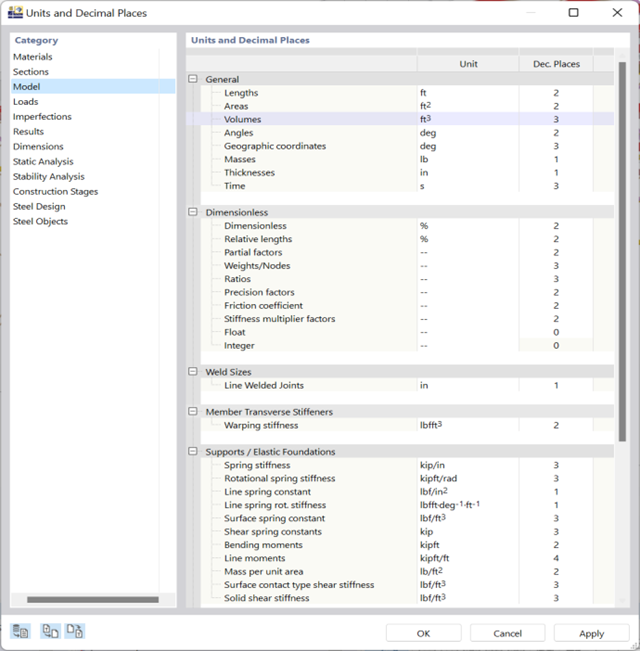
You can keep track of things with just a few clicks. A global dialog box manages the units for input data, loads, and results in RFEM or RSTAB, as well as in all add-ons.
You can save the settings and import them again later. In this way, it is possible for you to use different sections in steel and reinforced concrete structures, for example.
Go to Explanatory Video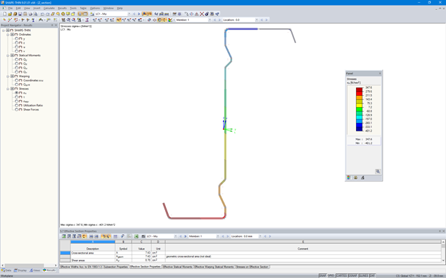
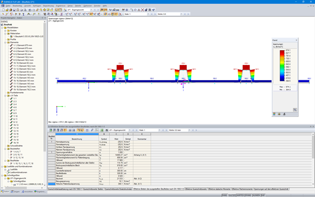
SHAPE‑THIN determines the effective cross-sections according to EN 1993‑1‑3 and EN 1993‑1‑5 for cold-formed sections. You can optionally check the geometric conditions for the applicability of the standard specified in EN 1993‑1‑3, Section 5.2.
The effects of local plate buckling are considered according to the method of reduced widths, and the possible buckling of stiffeners (instability) is considered for stiffened sections according to EN 1993‑1‑3, Section 5.5.
As an option, you can perform an iterative calculation to optimize the effective cross-section.
You can display the effective cross-sections graphically.
Read more about designing cold-formed sections with SHAPE-THIN and RF-/STEEL Cold-Formed Sections in the technical article "Design of Thin-Walled, Cold-Formed C-Section According to EN 1993‑1‑3".
Design of Thin-Walled, Cold-Formed C-Section According to EN 1993-1-3 More about RF-/STEEL Cold-Formed Sections
- Available for cold-formed L, Z, C, channel, top-hat, and CL sections from the cross-section database, as well as for general cold-formed (non-perforated) SHAPE-THIN-9 sections
- Determination of the effective cross-section considering the local buckling and the distortional buckling
- Cross-section ultimate limit state, stability, and serviceability limit state designs according to EN 1993‑1‑3
- Design of local transverse forces for webs without stiffening
- Available for all National Annexes included in RF-/STEEL EC3
- Module extension RF-/STEEL Warping Torsion (license required) for stability analysis according to second-order analysis as stress analysis including consideration of the 7th degree of freedom (warping)
_(2).png?mw=640&hash=0414bfe44045fc798e3774a0173332ca37424418)
General
- Beam to Column joint category: connection possible as joint of the beam to the column flange as well as joint of the column to the girder flange
- Beam to Beam joint category: design of beam joints as both moment-resisting end plate connections and rigid splice connections possible
- Automatic export of model and load data possible from RFEM or RSTAB
- Bolt sizes from M12 to M36 with strength grades 4.6, 4.8, 5.6, 5.8, 6.8, 8.8, and 10.9 as long as the strength grades are available in the selected National Annex
- Almost any bolt spacing and edge distances (a check of the allowable distances is performed)
- Beam strengthening with tapers or stiffeners on the top and bottom surfaces
- End plate connection with and without overlap
- Connection with pure bending stress, pure normal force load (tension joint), or combination of normal force and bending possible
- Calculation of connection stiffnesses and check if a hinged, semi-rigid, or rigid connection exists
End plate connection in a beam-column setup
- Joint beams or columns can be stiffened with tapers on one side or with stiffeners to one or both sides
- Wide range of possible stiffeners of the connection (for example, complete or incomplete web stiffeners)
- Up to ten horizontal and four vertical bolts possible
- Connected object possible as constant or tapered I-section
- Designs:
- Ultimate limit state of the connected beam (such as shear or tension resistance of the web plate)
- Ultimate limit state of the end plate at the beam (for example, T-stub under tensile stress)
- Ultimate limit state of the welds at the end plate
- Ultimate limit state of the column in the area of the connection (for example, column flange under bending – T-stub)
- All designs are performed according to EN 1993-1-8 and EN 1993-1-1
Moment-resisting end plate joint
- Two or four vertical and up to 10 horizontal bolt rows
- Joint beams can be stiffened with tapers on one side or with stiffeners to one or both sides
- Connected objects are possible as constant or tapered I-sections
- Designs:
- Ultimate limit state of the connected beams (such as shear or tension resistance of the web plates)
- Ultimate limit state of the end plates at the beam (for example, T-stub under tensile stress)
- Ultimate limit state of the welds at the end plates
- Ultimate limit state of the bolts in the end plate (combination of tension and shear)
Rigid splice plate connection
- For the flange plate connection, up to ten bolt rows one behind the other possible
- For the web plate connection, up to ten bolt rows possible each in vertical and horizontal directions
- Material of the cleat can be different from the one of the beams
- Designs:
- Ultimate limit state of the joint beams (for example, net cross-section in the tension area)
- Ultimate limit state of the cleat plates (for example, net cross-section under tensile stress)
- Ultimate limit state of the single bolts and the bolt groups (for example, shear resistance design of the single bolt)
In SHAPE-THIN 8, the effective cross-section of stiffened buckling panels can be calculated according to EN 1993-1-5, Cl. 4.5.
The critical buckling stress is calculated according to EN 1993-1-5, Annex A.1 for buckling panels with at least 3 longitudinal stiffeners, or according to EN 1993-1-5, Annex A.2 for buckling panels with one or two stiffeners in the compression zone. The design for torsional buckling safety is also performed.

- Import of materials, cross-sections, and internal forces from RFEM/RSTAB
- Steel design of thin‑walled cross‑sections according to EN 1993‑1‑1:2005 and EN 1993‑1‑5:2006
- Automatic classification of cross-sections according to EN 1993-1-1:2005 + AC:2009, Cl. 5.5.2, and EN 1993-1-5:2006, Cl. 4.4 (cross-section class 4), with optional determination of effective widths according to Annex E for stresses under fy
- Integration of parameters for the following National Annexes:
-
DIN EN 1993-1-1/NA:2015-08 (Germany)
-
ÖNORM B 1993-1-1:2007-02 (Austria)
-
NBN EN 1993-1-1/ANB:2010-12 (Belgium)
-
BDS EN 1993-1-1/NA:2008 (Bulgaria)
-
DS/EN 1993-1-1 DK NA:2015 (Denmark)
-
SFS EN 1993-1-1/NA:2005 (Finland)
-
NF EN 1993-1-1/NA:2007-05 (France)
-
ELOT EN 1993-1-1 (Greece)
-
UNI EN 1993-1-1/NA:2008 (Italy)
-
LST EN 1993-1-1/NA:2009-04 (Lithuania)
-
UNI EN 1993-1-1/NA:2011-02 (Italy)
-
MS EN 1993-1-1/NA:2010 (Malaysia)
-
NEN EN 1993-1-1/NA:2011-12 (Netherlands)
- NS EN 1993-1-1/NA:2008-02 (Norway)
-
PN EN 1993-1-1/NA:2006-06 (Poland)
-
NP EN 1993-1-1/NA:2010-03 (Portugal)
-
SR EN 1993-1-1/NB:2008-04 (Romania)
-
SS EN 1993-1-1/NA:2011-04 (Sweden)
-
SS EN 1993-1-1/NA:2010 (Singapore)
-
STN EN 1993-1-1/NA:2007-12 (Slovakia)
-
SIST EN 1993-1-1/A101:2006-03 (Slovenia)
-
UNE EN 1993-1-1/NA:2013-02 (Spain)
-
CSN EN 1993-1-1/NA:2007-05 (Czech Republic)
-
BS EN 1993-1-1/NA:2008-12 (the United Kingdom)
-
CYS EN 1993-1-1/NA:2009-03 (Cyprus)
- In addition to the National Annexes (NA) listed above, you can also define a specific NA, applying user‑defined limit values and parameters.
- Automatic calculation of all required factors for the design value of flexural buckling resistance Nb,Rd
- Automatic determination of the ideal elastic critical moment Mcr for each member or set of members on every x-location according to the Eigenvalue Method or by comparing moment diagrams. You only have to define the lateral intermediate supports.
- Design of tapered members, unsymmetric sections or sets of members according to the General Method as described in EN 1993-1-1, Cl. 6.3.4
- In the case of the General Method according to Cl. 6.3.4, optional application of "European lateral-torsional buckling curve" according to Naumes, Strohmann, Ungermann, Sedlacek (Stahlbau 77 [2008], pp. 748‑761)
- Rotational restraints can be taken into account (trapezoidal sheeting and purlins)
- Optional consideration of shear panels (for example, trapezoidal sheeting and bracing)
- RF-/STEEL Warping Torsion module extension (license required) for stability analysis according to the second-order analysis as stress analysis including consideration of the 7th degree of freedom (warping)
- Module extension RF-/STEEL Plasticity (license required) for plastic analysis of cross‑sections according to Partial Internal Forces Method (PIFM) and Simplex Method for general cross‑sections (in connection with the RF‑/STEEL Warping Torsion module extension, it is possible to perform the plastic design according to the second‑order analysis)
- Module extension RF-/STEEL Cold-Formed Sections (license required) for ultimate and serviceability limit state designs for cold-formed steel members according to the EN 1993-1-3 and EN 1993-1-5 standards
- ULS design: Selection of fundamental or accidental design situations for each load case, load combination, or result combination
- SLS design: Selection of characteristic, frequent, or quasi-permanent design situations for each load case, load combination, or result combination
- Tension analysis with definable net cross-section areas for member start and end
- Weld designs of welded cross-sections
- Optional calculation of warp spring for nodal support on sets of members
- Graphic of design ratios on cross-section and in RFEM/RSTAB model
- Determination of governing internal forces
- Filter options for graphical results in RFEM/RSTAB
- Representation of design ratios and cross‑section classes in the rendered view
- Color scales in result windows
- Automatic cross-section optimization
- Transfer of optimized cross-sections to RFEM/RSTAB
- Parts lists and quantity surveying
- Direct data export to MS Excel
- Verifiable printout report
- Possibility to include the temperature curve in the report

- Modeling of the cross-section via elements, sections, arcs, and point elements
- Expansible library of material properties, yield strengths, and limit stresses
- Section properties of open, closed, or non-connected cross-sections
- Ideal section properties of cross-sections consisting of different materials
- Determination of weld stresses in fillet welds
- Stress analysis including design of primary and secondary torsion
- Check of c/t-ratios
- Effective cross-sections according to
- EN 1993-1-5 (including stiffened buckling panels according to Section 4.5)
-
EN 1993-1-3
-
EN 1999-1-1
-
to DIN 18800-2
- Classification according to
-
EN 1993-1-1
-
EN 1999-1-1
-
- Interface with MS Excel to import and export tables
- Printout report
.png?mw=640&hash=eaf8e422e9b3dcfb04a920c1d3bf09c1bef0d59a)
General
- Beam to Column joint category: connection possible on the column flange as well as on the column web
- Beam to Beam joint category: optional arrangement of ribs on the opposite side
- Bolt sizes from M12 to M36 with the strength grades 4.6, 5.6, 8.8, and 10.9
- Arbitrary bolt hole spacing and edge distances
- Notching of the beam is possible
- Connection with pure shear loading, pure normal force load (tension joint), or possible combination of normal and shear forces
- Checking compliance with the requirements for pinned joints
- Check of the minimum and maximum bolt hole spacing and edge distances
Web cleat connections
- One or two vertical and up to 10 horizontal bolt rows possible at each leg
- Wide range of equal and unequal angles
- Possible to modify angle orientation
- Designs:
- Shear, bearing resistance, and tension design of bolts
- Shear, bending, and tension design of angles considering deduction of bolt hole
- Shear and tension design of girder web considering deduction of bolt hole
- Tension transmission into the column with the T-stub model
- Notching at the critical section
Fin plate connection
- One or two vertical and up to 10 horizontal bolt rows are possible
- Flexible size of the fin plate
- Location of the fin plate can be modified
- Designs:
- Shear and bearing resistance design of bolts
- Shear, bending, and tension design of fin plates considering deduction of bolt hole
- Stability analysis of long, slender fin plates
- Shear and tension design of girder web considering deduction of bolt hole
- Weld as fillet weld
- Notching at the critical section
End plate connection
- Two or four vertical and up to 10 horizontal bolt rows
- Flexible size of the end plate
- Location of the fin plate can be modified
- Designs:
- Shear, bearing resistance, and tension design of bolts
- Shear and bending design of end plates considering deduction of bolt hole
- Shear and tension design of girder web
- Tension transmission into the column with the T-stub model
- Weld as fillet weld
- Notching at the critical section
End plate connection with cleat
- Fixation of the beam by end plate with two bolts
- Flexible size of cleat and end plate
- Designs:
- Load introduction into the beam according to EN 1993-1-5, Chapter 6
- Support of the stabilizing moment by the bolts and welds at the end plate
- Cleat
- Cleat welds as fillet welds
- Tension transmission into the column with the T-stub model